Parting Line
A parting line is where two halves of a mould meet when closed. You can notice the parting line on injection moulded items as it appears as a slightly raised line on the part’s surface. When developing a 3D CAD model to be injection moulded, you may wish to spend some time thinking about where its parting line will be as the location can affect your part in several ways.
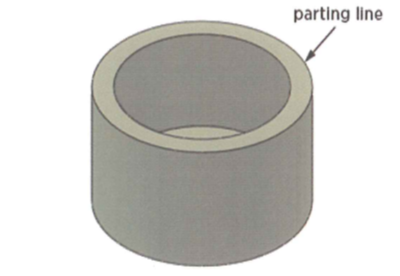
For some parts, the location for the parting line is obviously right down the middle, while for more complex parts it may not be so obvious. Take a simple cup for example. The outer face is formed by one mould half while the cup's inner surface and the brim will be formed by the other. The parting line occurs along the outside edge of the brim of the cup.
A part that can be made with a straight pull mould has all its features designed so that when the two halves of the mould pull straight away from each other, no elements of the mould become trapped and unable to pass through the plastic part. Undercuts on the part require pieces to pull out sideways, perpendicular to the direction of pull and add significant cost to tooling.
Whilst not always avoidable, the necessity of a side movement (or action) can sometimes be designed out as follows:

How to Determine a Parting Line During Injection Moulding
When determining where the parting line will be, it’s important to first determine the shape and position of the parting line on the mould. When the mould opening direction is established, it’s easier to determine where the parting line will be. There are certain considerations you must take when determining the parting line:
- Determine the opening direction of the mould relative to the part. It’s important to consider how the design of the part will look and which sides will carry the features of the product.
- Consider where to place components on the part. Because the plastic shrinks when it cools, the position might shift in the mould. You can ensure components stay in the right place by drafting the walls of the injection moulded part away from the parting line.
- Check the Design for Manufacturability (DFM) of your product which will suggest the best positions for your part line.
Core & Cavity
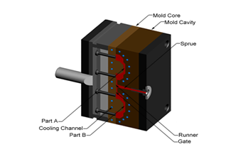
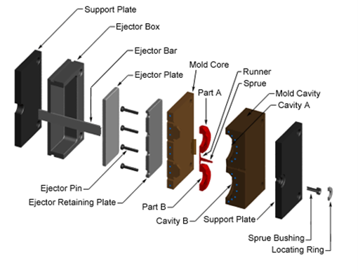
A mould tool consists of two primary components, the fixed half and the moving half. Plastic resin enters the mould tool through a sprue in the fixed half; the sprue bushing seals tightly against the nozzle of the injection barrel of the moulding machine to allow molten plastic to flow into the injection mould cavity. The sprue bushing directs the molten plastic to the cavity through channels that are machined into the fixed (Core Side) and moving halves (Cavity Side). These channels are referred to as runners. The molten plastic flows through the runner and enters one or more specialised gates and into the cavity to form the desired part.
As an example of an injection moulded core and cavity, let’s take a simple cup. To ensure the part stays in the moving half of the mould tool ready to be ejected, the mould is designed so that the outside of the glass is formed in the fixed half as a cavity, and the inside would be formed by the core of the mould. As the plastic cools, it will shrink away from the cavity and onto the core where it can then be carried over to the moving half on opening before being pushed off by the ejector system.

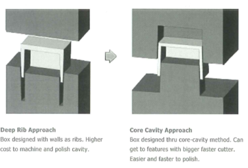
The Mould Core-Cavity Approach
Consider core-cavity approaches when possible as an alternative to deep sections. The illustrated core-cavity produces a similar geometry, but this mould will be faster and less expensive to manufacture. The quality of the final part will be improved as polishing is much easier on core-cavity geometries than down inside deep sections.
Feed
In order for the molten plastic to flow into the mould cavities, several channels are integrated into the mould tool design. First, the molten plastic enters the mould through a sprue. Additional channels called runners carry the molten plastic from the sprue to all of the injection moulding cavities that must be filled.
At the end of each runner, the molten plastic enters the cavity through a gate which directs the flow. The molten plastic that solidifies inside these runners is attached to the part and must be separated after the part has been ejected from the mould. However, sometimes hot runner systems are used which independently heat the channels allowing the contained material to remain molten and detached from the part.
Another type of channel that is built into the mould tool is a cooling channel. These channels allow water or oil to flow through the mould walls adjacent to the cavity and cool the molten plastic at the correct rate.

Ejection
The injection moulding process mainly uses pins to eject parts from the mould tool during production. Designers should be aware of the need to accommodate such pins. Pins of various sizes are used to push the plastic part out of the mould after it has solidified. The sizes, shape and arrangement of these pins are selected to minimise the impact on the part design. Sleeves, stripper plates, blades, up/away, up/in and bumping off are also alternative methods of ejection.

Product Assistance at Pentagon Plastics
At Pentagon Plastics, we provide high-level assistance for any plastic injection moulding project. We work with you during every stage of your project following your first enquiry. We offer a range of product assistance services including design for manufacture, product reviews, material considerations, tool designs and much more. Get in touch to see how we can help you.


